According to Henry David Thoreau, “the path of least resistance leads to crooked rivers and crooked men.” But in plastic injection molding, it leads to balanced filling patterns, more uniform shrinkage, less warp, smaller press sizes, and reduced cost when molding enclosures for medical devices.

Flow Matters
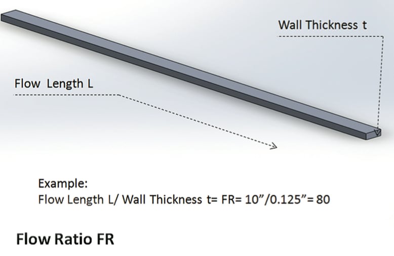
The flow ratio is the distance molten plastic must travel, divided by the wall thickness of the part (See Figure 1). It’s a simple approach to determine, without mold-filling simulations, whether a resin can reach all extremities of a mold simultaneously. This is the ultimate goal of flow balancing.
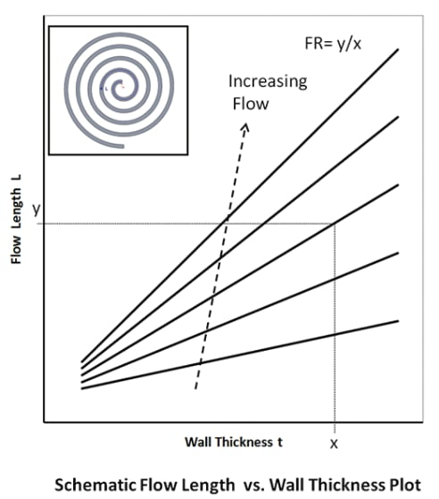
Ideal flow ratios are resin specific, but often are not provided by material suppliers. Based on experience, one can estimate future polymer flow performance, but it can vary, based on a range of factors, including part geometry. Detailed mold-filling simulations can be performed to determine a balanced flow pattern, but are costly and time-intensive. Another option to assess “flowability” is the spiral flow chart, which provides data about the maximum flow length of resins based on several variables, including melt temperature, mold temperature, injection pressure, and wall thickness. In this test, three variables are held constant, e.g., melt temperature, injection pressure, and mold temperature, while the fourth, the type of resin, varies to illustrate flow length. More than one resin can be characterized using this method (See Figure 2).
Improving Flow
To determine flow ratio, one must first determine wall thickness. Wall thickness is typically specified by the original equipment manufacturer (OEM) early in the design phase. Ideally, the contract manufacturer or molder is involved at that stage to influence the decision in terms of optimum moldability and manufacturability of the part.
Increasing wall thickness is the easiest way to decrease flow ratio and flow resistance. A thicker wall lowers resin viscosity, allowing the resin to flow farther without adding filling pressure. The lower the pressure, the smaller the press size and clamp tonnage—this decreases both stress on the part, as well as cost.

Let’s look at a sample part measuring 24" L × 18" W × 1.5" D. This part can be molded with conventional injection molding techniques. To do so, the sprue or gate is placed in the middle of the tool, resin fills the mold cavity, and molding is complete. But because of the rectangular shape of the part and the centered gate, the shorter sides of the part fill before the longer ones, including the corners. That increases the clamp force, so when the part is removed from the mold, it will tend to warp more because of molded-in stress. Its filling pattern will be less even. And it probably won’t meet all the cosmetic requirements. These issues all lead to costly secondary operations.
Now, if we take the same part and increase its wall thickness, the part has a lower flow ratio. With less resistance, the resin can flow farther and more evenly, allowing the part to be molded in a smaller press with lower tonnage. In turn, the smaller press causes less stress on the part and reduces warpage. But as mentioned above, increasing part thickness means more material, a heavier part, longer cycle time, and higher costs. But what if you only increase wall thickness locally, rather than across the entire part?
Understanding Flow Leaders
Here’s where flow leaders become useful. Flow leaders are areas within a part that extend from the gate to the areas of last fill. Their wall thickness is slightly more substantial than that of the main wall. Adding flow leaders creates paths of least resistance, improving flow without the added consequences. Instead of adding 10 percent more resin to the entire wall, only add 10 percent in strategic flow leader areas to create paths of least resistance. That results in only a two to five percent resin addition for the entire part. By elongating the filling pattern, both the width and length of the part fill at a similar rate. And because neither part weight nor cycle time is significantly increased, the part can still be molded in a smaller press using less tonnage.
Designing flow leaders into the part also eliminates the need for a second gate, which increases tooling cost, as well as the likelihood of additional knit lines. Cosmetics can suffer, requiring secondary operations and added cost.
Flow leaders are most commonly used in parts with:
- Large differences in length and width dimensions
- Extensions from the main body of the part
- Asymmetry, or one flow path that is longer than the others
- Large openings, requiring longer flow lengths (flow leader can also bridge over opening)
- Low flow resins, e.g., PVC
- Structural foam molding.
There are a few parameters to keep in mind when designing flow leaders into an injection-molded application. First, flow leaders are typically 10 to 25 percent thicker than the nominal wall, which reduces the flow ratio and improves flow without adding filling pressure. Adding more than 25 percent resin for the leader transforms it into a gas channel.
Second, because resin typically flows in a radial pattern from the sprue to the edges of the part, always design flow leaders to begin at the injection point for more balanced filling of the mold. And finally, be careful to blend them into the main wall of the part so there is a smooth transition between the varying wall thicknesses with no sharp corners. This helps to avoid transition lines or shadow marks on the cosmetic side of the part.
Restricting Flow

The exact opposite of a flow leader, a flow restrictor is an area or channel designed into the part to inhibit flow. Like a dam, flow restrictors redirect the flow of resin to areas of the part that are difficult to fill. They are most commonly used in injection molded panels that are three or more times longer than they are wide. Given that part geometry, restricting flow from side to side gives the resin a chance to reach all walls at or near the same time. This prevents pressure build-up in the lesser dimension, and allows the part to be molded in a lower tonnage press, since all extremities of the part now fill at the same time.
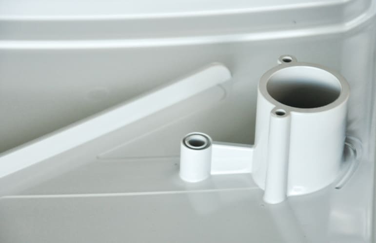
Flow restrictors can also be used to increase resin flow to other specific areas. Strategically placing a groove or flow restrictor behind a large rib or boss, for example, will create the pressure drop needed to force the resin up into the tall feature and pack it out (See Figure 3). Flow restrictors are also effective at filling features that are thinner than neighboring walls, like snap fits, or features that are far from the injection site.
When incorporating a flow restrictor into a part, reduce the wall stock by 10 to 25 percent for area flow restrictors and by 30 to 50 percent for channel flow restrictors. Blend the feature into neighboring walls to provide a smooth transition. And to effectively block resin flow, design the channel flow restrictor one- to one-half times wider than the local wall thickness.
Role of Computer Simulation
Now that computer simulation is more readily available, spiral flow test data for part design is not used as frequently. But it still plays an important role in pre-simulation assessment. Spiral flow test data is a simple way to determine the feasibility and cost of molding an application in a specified resin and/or with a given wall thickness. All you need to perform the test is the longest flow path in the part and the associated wall thickness. If wall thickness varies along the flow path, add the flow ratio values for the different segments to arrive at the overall ratio. Computer simulation should be used for more in-depth analysis, but it is often not readily available and comes with associated cost and timeframe requirements.
Summary
To follow the path of least resistance when designing injection-molding applications offers many benefits in terms of meeting both part requirements and profitability goals. Understanding flow ratio and how to incorporate features into the part and mold that will optimize flow allows manufacturers to:
- Produce large parts in smaller presses with less tonnage
- Provide more even and balanced filling patterns
- Create more uniform shrinkage with minimal warp
- Minimize material usage
- Eliminate secondary operations
- Reduce cost.
Finally, when OEMs involve their contract manufacturing and molding suppliers early in the design phase, they can minimize return trips to the tool shop by accurately predicting resin performance before steel for the mold is even cut.
This article was written by Michael Hansen, PhD, Senior Technical Development Engineer, Mack Medical/Mack Molding Company, Arlington, VT. For more information, visit www.mack.com .


