The product development process in the medical device field poses a demanding design environment for engineers and project managers. The design process often requires integrating the input from a multi-discipline team; in addition to engineers from various disciplines, team members might include medical doctors, life and health science practitioners, industrial designers, ergonomics specialists, and product marketers. Regulations and oversight typically involve government departments and various agency standards and approvals. Most critically, dealing with human life, well-being, and health requires a high level of quality, reliability, and effective product functioning not only to achieve satisfactory product performance, but also to avert product deficiencies and field failures that could cause safety issues and put users at risk.
 As a result, engineers and technical managers in the medical device sector are constantly seeking out tools that will provide them with additional technical insights, a thorough exploration of the design space, alternative and redundant checks on reliability, and communication techniques that can turn volumes of data and complex findings into a clear, concise, and meaningful explanation for team members from different disciplines.
Engineering analysis and virtual test software are enjoying wider uptake in medical design because they offer solutions in all of these areas. The ability to present predictive visualizations and animations of engineering entities like stresses, deformation, temperature gradients, and fluid flow patterns in 3D product models communicates design issues in a comprehensible way and makes data easier to grasp. The ability to easily change material properties, product geometry, and applied loads in simulations enables an exploration of material tolerances, manufacturing variability, design options, and performance boundaries. Plus, simulations bring another perspective and an additional check on hand calculations, benchtop prototypes, and test data.
One indication of the growing implementation of simulation software in the medical field is the U.S. Food and Drug Administration’s (FDA) initiatives in issuing standards, guidelines, and instructions on the use of computational modeling for device submission. In addition, since 2008, the FDA, together with the National Science Foundation and the National Heart, Lung, and Blood Institute (NHLBI), have hosted an annual workshop on computational methods. The following small sample of Finite Element Analysis (FEA) and Computational Fluid Dynamics (CFD) related topics addressed in this forum gives an idea of the breadth of applications receiving attention: computer-aided design of drug-eluting coatings, joint kinematics to predict prosthetic wear, modeling of fatigue behavior of Nitinol stents, and CFD analysis of coronary arteries. There are four data categories that device manufacturers submit and the FDA reviews in the pre-market setting to demonstrate required safety and performance: benchtop, computational, animal, and human.
Identifying Types of Mechanical Analysis Required for Medical Device Design
Identifying appropriate software is a matter of working through a hierarchy of criteria. For medical design, a sound system would be to consider criteria in the following order: analysis type, material property modeling capabilities, tools for achieving adequate fidelity, and finally, features needed for productivity and ease of use.
The software world groups solutions based on the engineering topic, the mathematical underpinnings used in setting up the problem, and the underlying numerical methods needed to arrive at a solution. Once the underlying physics of the problem is clear, the type of analysis can be defined. The types of mechanical analyses needed for medical device design are fairly extensive because these products serve the full range of medical disciplines and functions. Consider the diverse physical phenomena encountered in just a few medical disciplines — orthopedics, ophthalmology, dentistry, and cardiology. In addition to diversity in the medical disciplines, products fall into multiple functional categories: monitoring and diagnostics, replacement or augmentation of body functions, prevention of injury and disease, and tools and equipment for surgical and other procedures. A small random sampling of medical products illustrates this breadth: orthopedic bone screws, intraocular lenses, vascular stents, cochlear hearing implants, robotic surgical equipment, drug delivery devices, magnetic resonance imaging.
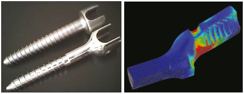
Among the analysis types cited previously, statics is the most widely used in FEA software. This is because it answers questions fundamental to every piece of hardware. (e.g. Is the structure capable of handling the expected loading? Where are the weak or critical points in the structure? What can be done to improve stress levels, reduce weight, save material, or make the part simpler?) An example of a statics analysis is provided by the following design study on orthopedic bone screws. An FEA linear statics analysis was conducted on a titanium implantable bone screw design to examine stress levels that would occur in the part during the insertion process. The case study determined that a redesign could produce a part with less stress for similar loading. In Fig. 1, a visual comparison examination of the two parts illustrates design differences as a result of the analysis.
Linear and Nonlinear Considerations
In statics analysis, linear behavior assumes deflection is directly proportional to the applied load, the highest stress is within the linear range of the material stress-strain curve characterized as a straight line from the origin, and maximum displacement is considerably smaller than the characteristic dimension of the part. Many applications of metals and plastics are intended to use just the elastic portion of the stress-strain curve and therefore fall into the linear category.
However, if these conditions are not present, then a nonlinear analysis is required. It is important to note that nonlinear effects can arise from a number of conditions. The material has nonlinear properties or the structure is operating beyond the yield point in the nonlinear plastic range of the material. Geometry changes resulting from deformations of the structure affect stiffness or applied forces. Or, there are changes in the boundary conditions resulting from contact. Medical device design often makes use of the nonlinear properties of different materials, vascular stents being one example (see the section of this article on Material Modeling Capabilities). Similarly, contact of different types is a common design condition. Nonlinear capabilities in analysis software are often used to expand the range of simulations that can be performed, adding a powerful, sophisticated dimension to design studies.
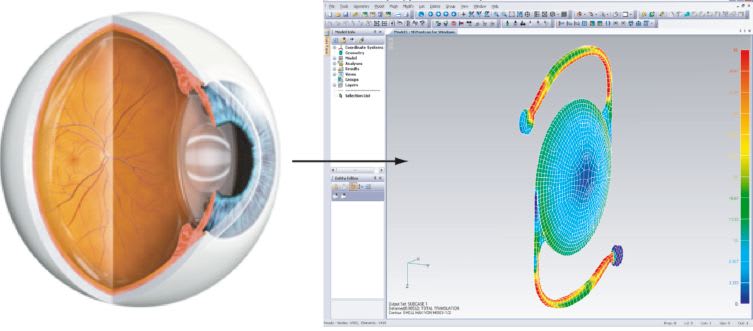
The design of intraocular lenses (IOL) and their implantation provides an example of a nonlinear buckling analysis and geometric nonlinearity. Buckling capabilities simulate the “snap through” action in which forces on a shell create an instability, resulting in a transition from concave to convex topography. In addition, the lens is highly flexible and is pushed or supported by surrounding media which requires accommodating geometric nonlinearity and modeling of 3D contact.
Material Modeling Capabilities for Healthcare Simulations
Consider the range of materials medical design engineers might use: metals like biocompatible titanium and shape memory alloys like Nitinol with hyperelastic properties; thermoplastics and polymers like polyether ether ketone (PEEK) for mimicking the structural behavior of bone, and medical-grade ultra-high-molecular-weight polyethylene (UHMWPE) for hip, knee, and spine implants; silicon-based organic polymer polydimethylsiloxane (PDMS) with viscoelastic behavior used in contact lenses; composites ranging from common glass fiber reinforced systems to special formula carbons, Kevlar and matrix systems with all manner of ply layups, orientations, and local reinforcements.
Composites, because of their orthotropic nature, require a degree of sophistication not required with isotropic metals. In addition, the engineer must not only look at stresses and deformation, but also at specific failure criteria to determine the order of ply failure, and assess the fracture potential of the composite structure.
Finally, there are biological tissues: skin, bone, and muscle. Typically, these require using a hyperelastic idealization such as a Neo-Hookean, Mooney- Rivlin, Ogden, Yeoh, or proprietary generalized polynomials. Taken together, these materials represent a full range of material behavior — elasticity, plasticity, hyperelasticity, thermoelastic creep, brittle behavior, and shape change. The appropriate capabilities must be represented in the software’s material modeling.
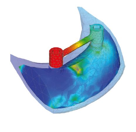
An illustration of material capabilities being used in an FEA study can be seen in a mandible implant case study. The simulation required comparing the behavior of numerous combinations of human bone, metallic implant screws, and bar clip attachments to arrive at a successful biomechanical solution. The mandibular bone was fully described with cortical (compact morphology) and trabecular (spongy morphology) structures fully defined. (See Fig. 3.)
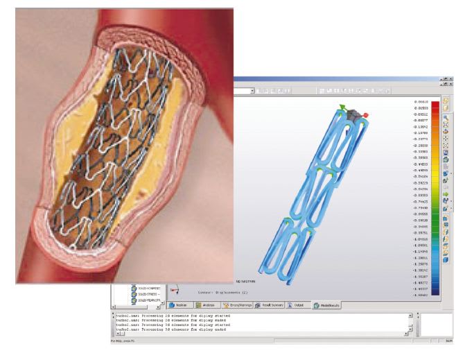
Nitinol is used in vascular stents because of its shape memory and superelasticity properties. (See Fig. 4.) Elastic deformation of metals like stainless steel is limited to a strain of about 1%, and elongation increases linearly with the applied force. In contrast, Nitinol can be elastically deformed to about 10% in a nonlinear way. When the deforming stress is removed, the strain is recovered at lower stresses. The loading and unloading cycle is characterized by a notable hysteresis. Interestingly body materials like hair and bone exhibit similar behavior. The ability to model this highly nonlinear behavior is essential for FEA simulations.
Software Features to Enhance Fidelity
Thus far, we have looked at defining FEA software by analysis type with consideration of linear and nonlinear behavior, and material property modeling. In this section, we examine some tools and features that help achieve better fidelity in simulations. In constructing the FEA model, choosing how to represent the forces applied to a structure is fundamental to matching real world behavior. Presumed or simplified load vectors and distributions can be mischaracterized, resulting in low fidelity of the FEA simulation and poor accuracy. However, the option exists in sophisticated FEA software of using a surface contact feature. For example, in NEi Nastran from NEi Software (Westminster, CA), using multiple deformable bodies and defining which surfaces on parts will be in contact with each other, the solver has the capability to determine the resulting forces and load distribution. This produces an accurate simulation of stress and deformation. Plus, with tools like Automated Surface Contact Generation (ASCGTM) and Automated Edge Contact Generation (AECGTM) in NEi Software’s FEA portfolio, the increase in fidelity and accuracy can be an efficient, productive, and economic exercise.
Another example of a sophisticated approach in FEA simulation that can improve fidelity and accuracy is in the area of impact analysis, which is used for low velocity impact and drop tests. Automated Impact Analysis (AIA™) from NEi Software provides a thorough and physically realistic simulation of impact by taking into account surface contact, the time duration of the impact, and the vibration characteristics of the colliding bodies. This is a much more comprehensive and useful treatment of the real world physics than the more simplistic imposition of force at a point that may be found in other alternative solutions for impact and drop test simulations. AIA is a simulation tool that makes a complex analysis easy while retaining the complexity of the underlying physical phenomena.
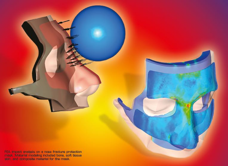
An example of an impact analysis is provided in the design of a nose fracture protection mask. (See illustration on pg. 4). The project required material modeling capabilities for bone, soft tissue skin, and a composite mask material. FEA results showed the distribution of compressive stress on the facial bones guarded by the mask. This simulation was conducted by Renato Archer Information Technology Center.
A Note on Multiphysics
At the beginning of this article, medical design problems were sorted into: Structural Mechanics, Heat Transfer, Fluid Mechanics, and Acoustics. It should be noted that some simulation problems cannot be adequately modeled by segregating them into one category and using a specific FEA or CFD analysis tool. Certain physical problems require accounting for the interaction of multiple phenomena, for example as occurs with thermal-structure or fluid-structure interaction.
Fluid-structure interaction (FSI) is a complex engineering analysis that requires coupling FEA and CFD. In an FSI analysis, the solid surfaces act as interfaces between the fluid and solid domains to provide the transfer of mechanical loads. The CFD solution provides flow field solutions for pressure, and then the FEA solver calculates solid deformations based on the CFD results. The deformed solid surfaces will in turn constitute a new boundary for CFD calculation, which leads to a different pressure loading. The FSI analysis executes a fully coupled iterative solution at each time interval. Incorporating, coupling, and accounting for the physics of both solid and fluid parts are fundamental to FSI analysis. As an example, FSI is used in modeling certain applications of blood flow in arteries.
Summary
The design of medical and healthcare products can require many different types of engineering analyses and material considerations. FEA and CFD software are valuable additions to a design team’s tools for performing analysis, simulation, and virtual testing in support of design projects. Establishing a hierarchy of criteria for software is needed to produce a successful match with design needs. The necessary first step is an understanding of the underlying physics and the corresponding engineering analysis type. This should be followed by defining the properties of the materials that will be used in the simulation and examining the software’s capability to accommodate the material behavior. Consideration of the need for nonlinear analysis and software’s capabilities in surface contact can establish appropriate levels of fidelity. These criteria represent a high-level framework for identifying and specifying engineering analysis and simulation software candidates for medical device design. Further considerations are required to develop a complete specification and would include examining the performance of software element types, mesh quality, and the accuracy of the underlying solvers.
This article was written by Dennis Sieminski, Technical Marketing for NEi Software, Westminster, CA. For more information, Click Here to explore NEi Software's Knowledge Base Center for White Papers and case studies to explore the full range of FEA and CFD software for medical design and topics on achieving accuracy in simulation studies. Visit www.medicaldesignbriefs.com/component/content/article/13742 to view video examples of FEA analysis.