

Film cast tubing and liners have been used for more than 30 years in catheter-based medical device products. Originally developed and introduced in the early 1990s, there are currently 10 film cast tubing manufacturers, half of which were acquired by larger companies, all located within the Continental United States. Even with these acquisitions and time, the technology has not advanced much beyond its original conception. Nowhere is this better exemplified than in film cast PTFE liners and tubing. Many of the same problems associated with the PTFE film cast products 20 years ago are still widely seen today.
This article explores how the film cast process manufactures micro tubing products from liquid polymer coatings, then defines three important test methods and specifications that are needed to optimize film cast PTFE’s quality and material strength properties. Finally, it looks at some important film cast process idiosyncrasies that few consider but that can have a big effect on the final product’s quality.
Process Overview: Precision Tubing from Liquid Polymer Coatings
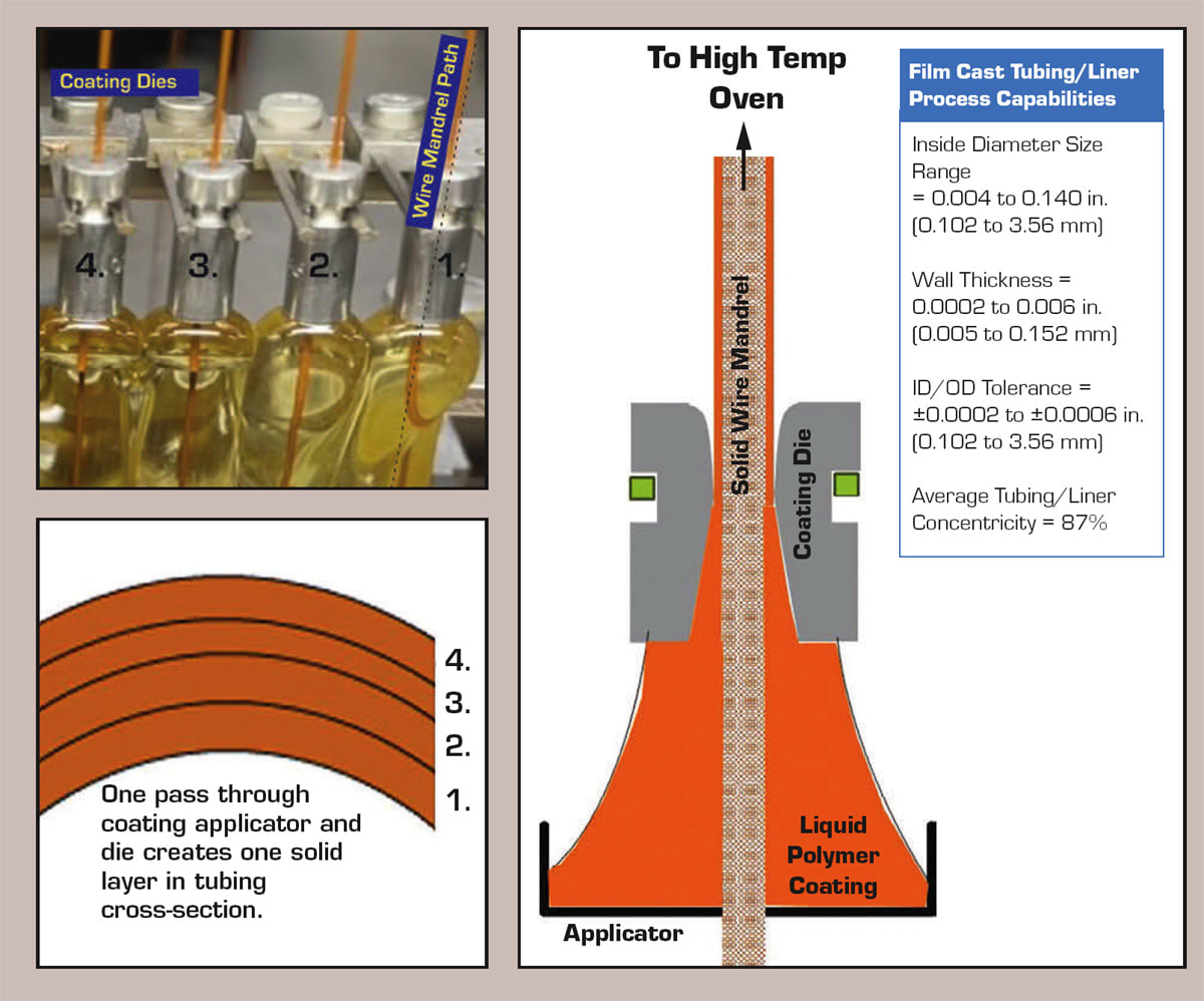
The film cast micro tubing process takes different liquid polymer coatings (PTFE, polyimide, Pebax, polyurethane, etc.), and turns these liquid coatings into solid micro-sized tubing products with ultra-thin wall thicknesses, and extremely small tolerances. As part of the film cast process, liquefied polymers are coated over and molded around the outside of a solid metal wire mandrel. The film cast process begins with the application of a thin layer of liquid polymer coating over a solid metal wire mandrel, after which the liquid coating is cured into a solid polymer using infrared heat. This process is then repeated, adding successive layers of material until the desired tubing wall thickness is achieved. Figure 1 does not show PTFE specifically but is meant to be a generalized process description.

Each time a section of wire length moves through the coating applicator, it picks up a layer of polymer coating. Each coating pass creates a new solid layer of polymer within the tubing’s cross-sectional area. Once the tubing product is completed, the continuous mandrel wire will be cut to length, then the mandrel wire is removed using elongation (see Figure 2).
Coating Solidification Process
This section reviews the film cast PTFE coating solidification process and defines three primary specifications that will optimize film cast PTFE material strength properties.

Film cast PTFE liners are made using a water dispersion coating, which is a heterogeneous mixture of deionized water, sub 1 μm PTFE powder, and a surfactant (detergent). The coating is applied to the solid surface of the mandrel wire and heated. First the water, then the surfactant will volatilize and boil off leaving only the PTFE powder particles (see Figure 4).

Further heating from the higher temperature oven zones as hot as 400–900 °F (204–482 °C) causes the sub-1-μm PTFE particles to expand to over 20 percent of the room temperature volume (see Figure 5). (Note: While part of this temperature range exceeds the 400 °C decomposition temperature of PTFE, the film cast process equipment is designed to prevent the PTFE from breaking down and releasing fluorene gas.)
The individual PTFE particles will quickly expand when they reach temperatures around 620 °F (327 °C), which forces each particle against one another. As these PTFE particles expand, the PTFE chains around the outer surface of each PTFE particulate begin to “unpack,” becoming less dense, and leading to the formation of lose PTFE fibrils all along the PTFE particles’ outer surface. As the individual PTFE particles are pushed up against one another, these less dense, fibrillated, and partially melted particle surfaces become bonded to one another. This process is known as sintering, where particles outside surface is essentially activated, so when two or more particles are pressed together, they bond.
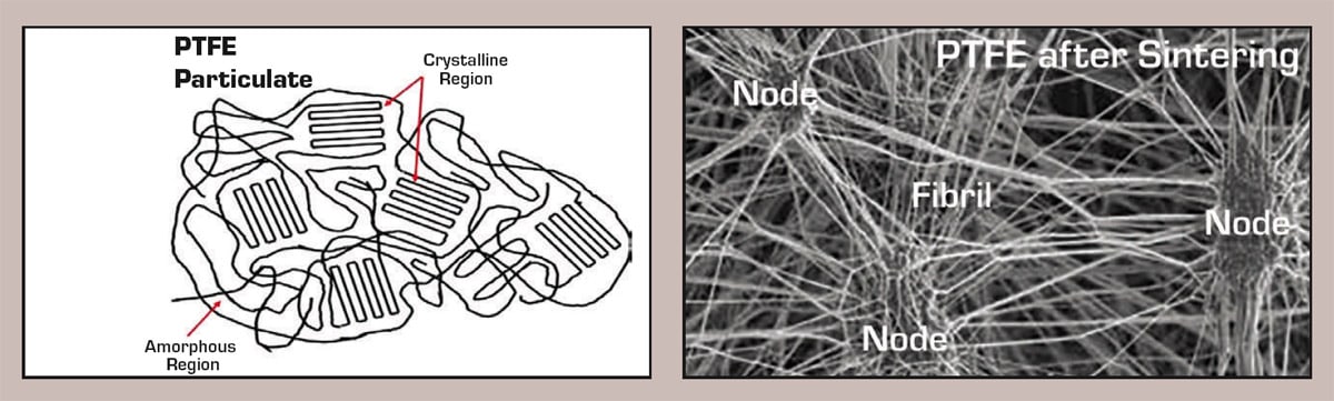
When the PTFE coating cools, each particle will then try to shrink back to its original volume, and it is this “volume recovery” of PTFE that creates an amorphous and translucent, yet fully sintered PTFE film. While the PTFE wants to contract back to its original room temperature volume, the high temperature sintered bonds between the different PTFE particulates have already been established. So, as the PTFE particle volume contracts, it maintains these sintered bonds by the formation of PTFE fibrils that run between two or more particles. The source of these PTFE polymer chains that make up the fibrils originate from the two particles that were once in contact with one another. The crystalline region of the original PTFE particles become unwound or unstacked, forming these PTFE fibrils. The resulting material has a node-fibril microstructure and looks like the images in Figure 6 labeled “PTFE After Sintering.”
While there is still some crystallinity left within these nodes, most of the space within the film cast PTFE is taken up by fibrils, and therefore, this type of PTFE is referred to as being amorphous. Being amorphous allows for the transmission of visible light and other wave-based energies, such as ultrasound and ultraviolet.
Verifying Sinter Bond Quality

The underlying force that drives the creation of sintered film cast PTFE is radiant infrared heat energy, and the application of this heat-energy is best evaluated using tensile testing on the finished PTFE tubing or liner. This means the finished fully cured PTFE tubing must be removed from its wire mandrel, and then tensile tested to produce a stress-strain curve. This stress-strain curve illustrates how effective the heat energy was in sintering together individual PTFE particles from the original liquid coating into one solid homogeneous film (see Figure 7).
From the stress-strain curve, the most important value that should always be defined as the primary finished product specification is the tensile break stress (in PSI). This tensile-based specification is usually written as a minimum value, meaning the tensile break stress cannot be less than the quantity given. The internal bond strength between nodes and fibrils is evaluated by elongating them until mechanical failure and separation occurs. Elongation and elastic modulus should be recorded, and watched, but for sintered film cast PTFE, a sufficiently high break stress will not be reached unless the material elongates enough.
No other test value can truly quantify the effectiveness of the sintering process better than the tensile break stress. It is important to point out that this specification is defined as a stress value, which is force per area and requires the use of PSI as its unit of measure. Regardless of the variations in the cross-sectional area amongst different tubing sizes, the minimum break stress value is always the same regardless of dimensions.
Visually looking for and finding cracks, even when they are present, in a translucent medium is neither quantifiable nor repeatable. Instead, a repeatable strength-based test should be used to evaluate the quality and quantity of the sintered bonds that create the final homogenous film material. A good film cast PTFE cure quality is indicated by a tensile break stress between 4,000 and 5,000 PSI.
PTFE Etching
PTFE, without exception, always requires etching to bond to it. PTFE etchant works by dissolving the organic salt sodium naphthalene (Na+C10H8–) into the solvent diethylene glycol dimethyl ether or “Diglyme.” The sodium naphthalene ionizes in the solvent, and the sodium ion (Na+) reacts with a fluorene atom along the PTFE polymer chain forming a sodium fluoride (NaF) molecule. This formation of sodium fluoride removes one fluorene atom from the exposed molecular surface of PTFE. This removal of a fluorene atom leaves a carbon without a filled valence electron and therefore forms a free-radical. This removal of fluorene and formation of a free radical creates a polar attraction at the PTFE’s outer surface, which allows for bonding with other polymer materials.
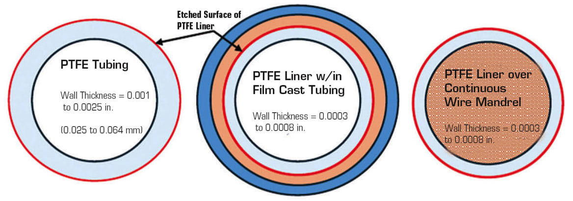
PTFE Etch Quality and Its Effect on PTFE Material Strength Properties. When a film cast PTFE wall thickness is less than 0.001 in., the etch quality has an extremely large effect on the overall strength and tear resistance of the PTFE liner. Film cast PTFE liners can be made extremely thin, sometimes with wall thickness of only 0.0003 in.; therefore, a significant amount of its mechanical strength is gained from the bond quality between the PTFE liner and the rest of the overall catheter body. There must be a strong bond between the top surface of the etched PTFE Liner and the remaining wall thickness of the catheter shaft. The strength of this bond is significantly affected by etch quality; therefore, etch quality must be tested and verified.

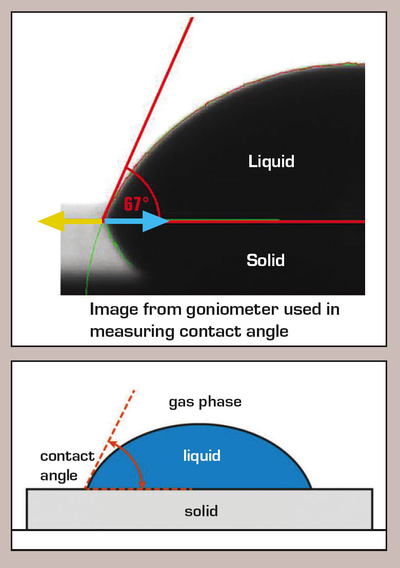
PTFE Etch Quality Evaluation Using Contact Angle Testing. When a drop of pure water (deionized water) is placed on a flat surface, a contact angle forms between the water drop’s outer two profile edges and the solid material that the water drop is resting on. Magnifying one of these contact angles provides a method to evaluate film cast PTFE’s etch quality or how well other liquid coatings will “wet” or attract to the etched PTFE surface. The better the PTFE’s etch quality, the more polar surface attractions are formed at this etched surface. This greatly improves surface wetting from any applied liquid coating, which results in a maximized bond strength between the PTFE liner layer and the remainder of the shaft’s wall thickness.
The contact angle test is an indicator of the forces that are acting on the water droplet. When a drop of deionized water is placed on any surface, the water will feel an attraction from the solid surface it is on, but it will also feel an internal attraction to itself. This tug of war between two different and opposite attractive forces can be used to evaluate and measure the contact angle (θc) (see See Figure 11).
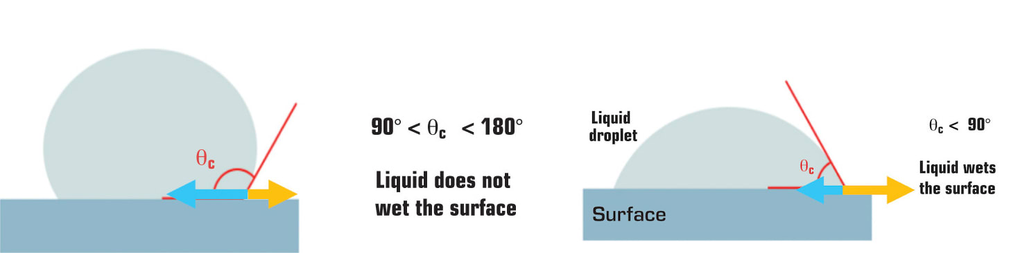
In Figure 11, (θc = contact angle) are graphics of two DI water droplet images from a goniometer contact angle test. In a simplification of Young’s equation (γ SG = γ SL + γ LG cos(θ° contact angle) ): The blue arrows represent the DI water’s internal self-attraction force or surface tension, and the orange arrows represent the DI Water’s attraction to the surface material it is resting on.
Young’s wettability equation [ γ SG = γ SL + γ LG cos(θ° Contact Angle)] describes a water droplet that is in equilibrium with the solid that it rests on and the gas environment that surrounds it. Assuming air pressure and temperature are constant, and according to Young, liquid-to-solid wettability begins at a 90° contact angle and continuously gets better as you approach a zero (0°) contact angle.
This means that the largest contact angle value that can be accepted in a specification for etched PTFE is 90°. To add some “safety factor,” set the maximum contact angle specification at an 80–85°.
Contact angle testing is usually performed on a flat surface. This is problematic when testing micro diameter tubing products. Because the tubing cannot be made flat, use a small enough water droplet that approximates a flat surface during the test. When performing contact angle test on tubing with an outside diameter less than 0.025 in., use a goniometer with a droplet size of 1 to 2 μL.
Tear and Damage Resistance
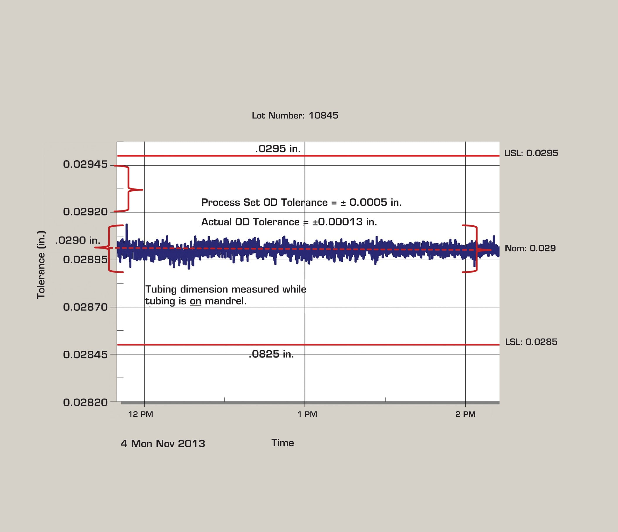
Film cast PTFE inner catheter shaft liners tend to be much less prone to tears and damage than other tubing types, simply because the ID tolerance provided by film cast [±0.0003 in. (±0.008 mm)] is usually half the tolerance of tubing made with other processes. Essentially film cast PTFE liners avoid tears and damage, rather than resisting tears and damage (see Figure 12).
While the figure shows the tight tolerance associated with the outer diameter of a PTFE liner, the graph also reflects the tight tolerance of the wire mandrel’s OD or the PTFE liner’s inside diameter (ID). Since the PTFE coating is extremely thin and conforms closely to the surface, these measurements also indicate the ID’s consistency.
Manufacturing Problems
Surface Quality and Cleanliness. All film cast tubing designs (including PTFE) always start with a solid metal wire mandrel. Even so, in most film cast tubing orders, the mandrels and mandrels’ specifications are often not even considered by either the customer or manufacturer.
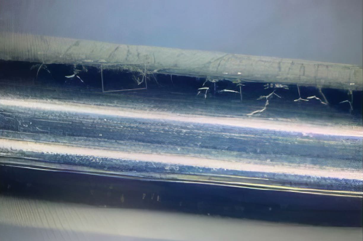
This solid metal wire mandrel serves as a continuous extrusion die-pin that maintains the tubing’s ID dimension, as well as the tubing’s overall precision. Damage and uncleanliness on the wire mandrel’s outer surface will most likely be imprinted into the inside surface of finished tubing product and may also damage the inside of the tubing upon mandrel wire removal (see Figure 14). See Graphic Below:
All dirt and or damage that is on the surface of the wire mandrel will have a high probability of being reflected on the inside surface of the film cast tubing that is being built around this mandrel. In the ISO Quality Standard 14971 for Risk Management, risk is defined and calculated as the probability of occurrence multiplied by the severity of that occurrence. When mandrel wire has surface problems, the probability that these problems will be imprinted into the ID of the tubing is over 90 percent (see Figure 15).


These wire mandrel surface defects cause localized spots of variable wall thickness in the final film cast tubing product. When a wire mandrel defect is convex, the wall thickness will be slightly too thin at this spot. When the defect is concave, the tubing/liner wall thickness will be too thick. These localized spots of high and low wall thicknesses, create variability in the tubing’s strength and distorts straightness after the tubing has been removed from the mandrel.
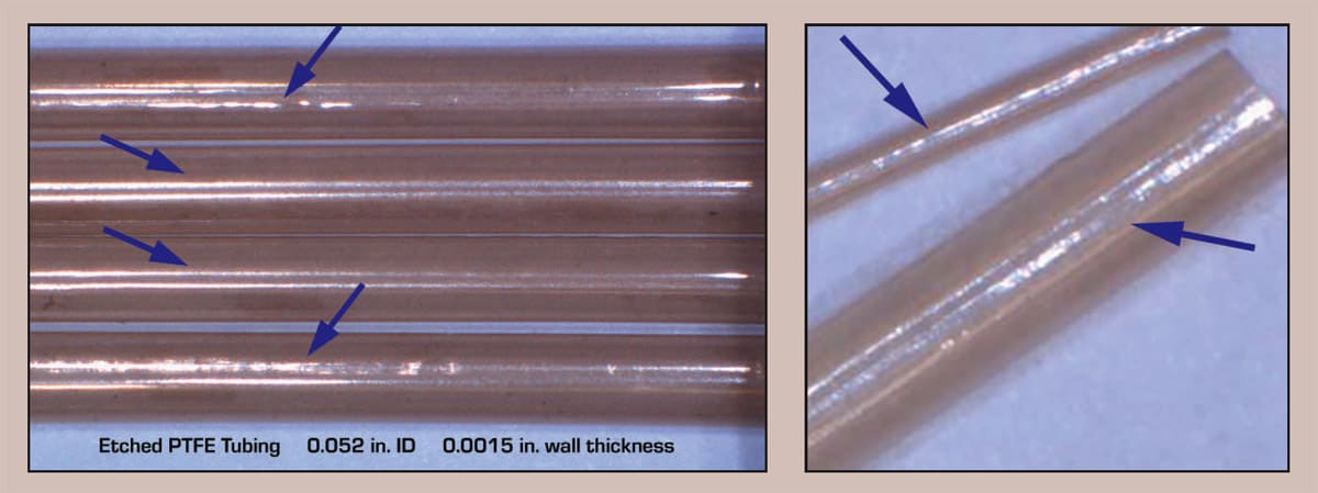
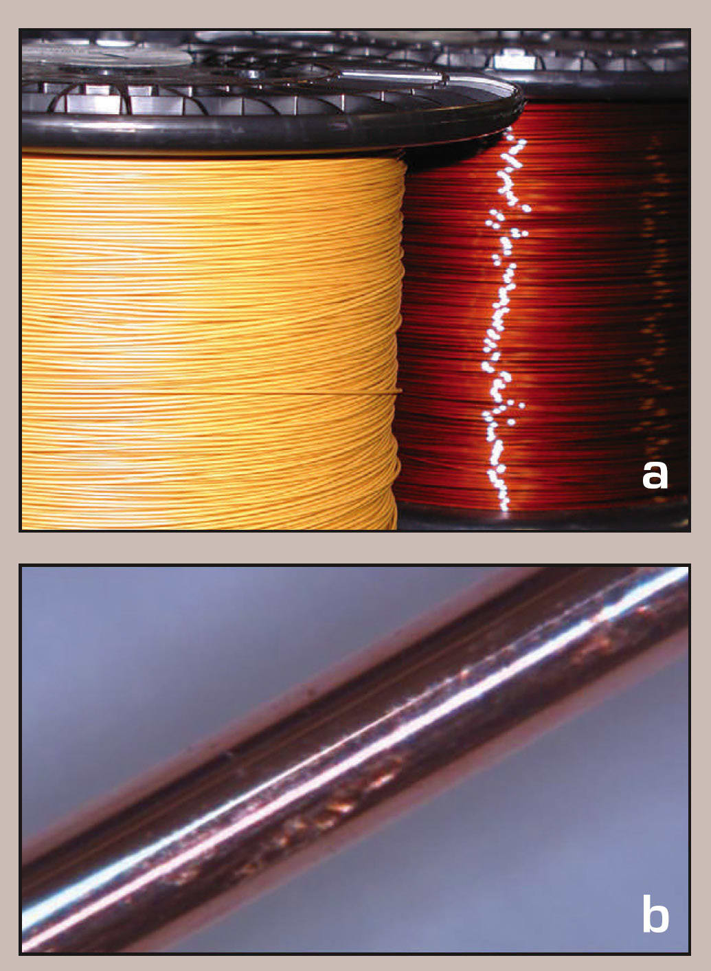
This variability in the wire mandrel’s surface condition can be seen in the glare of the two photographs in Figure 16 of the six pieces of film cast PTFE tubing. In the picture on the left with four lengths of tubing, notice the glare of the two middle tubes. These look very different when comparing them to the glare coming off the remaining four tubing lengths of PTFE.
It is important to keep in mind that PTFE tubing in the two photos is not necessarily defective; rather no matter how small the wire mandrel surface inconsistencies are, the film cast process will mold these inconsistencies into the ID of a finished product.
Film Cast Metal Mandrel Manufacturing: Wire Drawing

Wire drawing is the process that manufactures the wire mandrel and determines the mandrel’s outer dimensions, surface quality, and surface consistency. The wire mandrel is created using the process of pulling wire through wire drawing dies to reduce its diameter. Wire drawing is essentially controlled cold work elongation of a continuous wire with a round cross-sectional profile. Round wire is pulled through one or more dies to reduce down its diameter to the targeted size or tubing ID dimensions. As the wire is pulled through each die, its diameter is reduced by around 0.001 in. (0.025 mm). As the wire is pulled through each die, a water/synthetic-oil lubricant emulsion is applied to each die for cooling as well as to lubricate the wire traveling through the die (see Figure 17).
Wire drawing is an old and very industrialized process. Industrial-based wire drawing companies tend to see things from a very nonmedical perspective when it comes to cleanliness. The wire drawing process is not inherently dirty; rather a wire drawing process without the proper controls and maintenance can become very dirty. This is especially true in regard to the system that applies the wire drawing lubricant/coolant during the wire drawing process.
Improving Surface Quality and Cleanliness
When it comes to producing a film cast mandrel wire with an excellent surface finish and excellent cleanliness, there are three important technical capabilities that the wire drawing equipment and process must have.
Filtration of Wire Drawing Liquid Lubricant/Coolant. The action of drawing down metal wire produces a good deal of dirt and foreign matter such as oxides, carbonized organics, micro-sized metal flakes, polymer clothing fibers, etc. This dirt material must be filtered out of the liquid coolant/lubricant using a 5–10-μm filter. This filtration process takes place within the wire drawing equipment and removes the dirt that can be deposited on the wire and drawn down into its surface.
Post Wire Drawing Burnishing or Polishing Process. The next process capability takes place outside the wire drawing equipment and in a separate process distinct from wire drawing. In this polishing process step, the mandrel wire moves through a series of spinning or static wire dies that are especially designed to polish or burnish the outside surface of the metal wire. Any digs, gouges, edges, or loose metal particles on the surface of the wire are polished down and or removed using this method. A polishing or burnishing die does not reduce the OD of the wire, if it does, then it is not a polishing die.
Wire Mandrel Cleaning. The mandrel wire’s surface should be cleaned before and after the burnishing or polishing process. These two cleaning steps take place outside of the wire drawing equipment and use specialized equipment.
Damage Caused by Wire Winding
Spooling is another film cast processing step that has an incredibly large effect on the final product but often goes unnoticed. Film cast PTFE liner is often sold on the wire mandrel it is made on, either in a cut and straightened condition or wound on a spool. Even when a customer purchases film cast PTFE on a spool, the wire mandrel is always cut and straightened prior to building the rest of the catheter’s wall thickness over it.
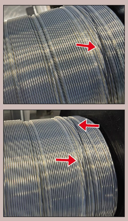
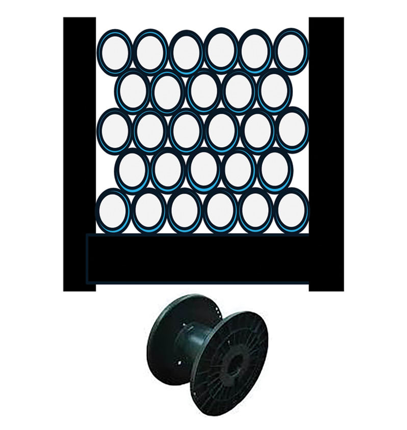
After applying the PTFE or any other polymer coating, the spooling packages and preserves the film cast tubing or liner. The film cast process is not just protecting the wire, but more importantly, it is protecting the thin polymer coating around the wire. The equipment that puts the wire on a spool is called the take-up. The film cast polymer coating over a mandrel wire can easily be damaged by this take-up equipment if certain technologies are not employed. See the two images in Figure 18 showing examples of how poor wire spooling can damage film cast PTFE as well as any other film cast polymers. Wire drawing is a very well-developed process, and there are several wire processing technologies that would literally eliminate these winding or spooling problems (see Figure 19).
Conclusion
Despite more than three decades of use in catheter-based medical devices, film cast tubing — particularly PTFE liners — remains largely unchanged since its introduction in the early 1990s. Many of the same performance challenges persist, high-lighting the stagnant evolution of this technology. This article has examined how film cast micro tubing is produced from liquid polymer coatings, outlined key test methods and specifications for improving material strength and consistency, and explored subtle but critical process factors that are often overlooked. Together, these insights underscore the need for renewed focus and innovation in film cast PTFE manufacturing.
This article was written by Brett Steen, Engineering and Technical Consultant, Chattanooga, TN. Steen designs, builds, installs, and improves film cast tubing technology with over 25 years of experience who specializes in building catheter-based medical devices that are 7 French and smaller. He is currently looking for partners in Asia who are interested in building a film cast micro tubing process outside the United States. He can be reached at