Board cleaning is perhaps one of the most overlooked aspects of printed circuit board (PCB) assembly. But savvy medical electronics original equipment manufacturers (OEMs) have a keen sense of the importance it plays to ensure their products are free of miniscule flaws, defects, debris, and dust. In special cases, critical examinations must be performed to assure the correct cleaning solvents and processes are implemented to avoid damaging contaminants.
Advanced medical electronics PCBs are especially subject to these particular sensitive issues. So, OEMs are taking an even closer look at today’s board cleanliness and demanding ultra-clean boards due to newer and smaller packaging and ever-shrinking PCBs. In particular, they want to avoid product flaws or failures occurring due to either new cleanliness challenges or the use of inadequate PCB cleaning solvents and practices.
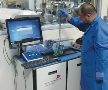
In some cases, OEMs want to evaluate conventional de-ionized (DI) water with newer, different chemicals for batch cleaning, test the results, and perform Ionograph testing to determine which cleaning methodology is best for their products. (See Figure 1)
Bubbles Creep in
While standard PCB cleaning practices are adequate in most instances, there are times when the EMS provider and medical electronics OEM must take a step back, such as when an unexpected problem occurs due to insufficiently clean sub-assembly circuits. At that point, both the EMS provider and the medical electronics OEM should work closely to begin to formulate the DOE.
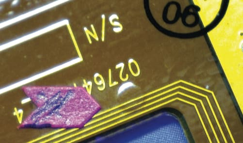
Like this particular sub-assembly, growing numbers of medical electronics PCB designs are high, and ultra-high frequency assemblies that demand special cleaning processes. And like the flex circuit discussed here, some PCBs for handheld and portable applications are so extensively and densely populated with small, complex packages in a remarkably small area that DOEs must be ushered in to resolve design or assembly issues, such as cleaning. First, however, special cleaning processes must be applied before DOE practices are exercised.
Target Requirements
Special cleaning processes for high-frequency assemblies, including those for medical electronics PCBs, have the following target requirements.
(a) The removal of ionic contaminations to the highest possible level, basically, to make the assembly in the purest form as much as possible.
(b) Use of a low surface tension solvent to achieve better penetration specifically under the low profile component packages. These miniscule packages don’t have too much room or have too thick or too big of a ball or bump. Low surface tension solvent is necessary so that those chemistries can go underneath those small devices and do the extra required cleaning.
(c) Use environmentally sensitive material, something that is not too corrosive or detrimental to the environment. Some chemicals used in some special cleaning chemistries could include a combination of a harmful solvent such as sulfuric acid, which is detrimental to the environment. Hence, careful choices about certain environmentally sensitive materials must be made.
(d) These solvents should be used with ultrasonic cleaning at stage one or first pass cleaning, and ultrasonic machines should be used.
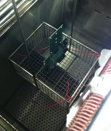
(e) If the cleaning isn’t performed as per the customer’s requirement, the second stage of ultrasonic cleaning is conducted using de-greaser machines to do the job. (See Figure 3)
Collaborating with a Medical Electronics OEM
A six step-by-step method was used in this DOE to arrive at a satisfactory solution. It begins with the method normally used, but with extra scrutiny to determine if anything was missed.
Step one: The first step was to subject the flex circuit to a de-ionized (DI) water cleaning. In this case it didn’t resolve the issue. Batch cleaning then followed.
Step two: An Ionograph test was performed. However, cleaning results weren’t as effective and as pure as expected.
Step three: The assembly team returned to the drawing board. Brain storming followed and other alternatives were considered.
Step four: Discussions about possible solutions were conducted between the OEM customer and assembly personnel. Another possible answer was agreed to keeping in mind the failed approaches thus far in this step-by-step process.
Step five: The methodology and specifications were changed based on out-of-the-box thinking, and the DOE was re-done.
Step six: It’s well understood that the DOE solution is sometimes within uncharted territory. But both the OEM and assembly personnel continued until the right DOE solution was reached.
DOE solutions arise from special EMS provider in-house methodologies and techniques. The proper solution may not be immediately obvious. But when certain, well-proven experienced thinking and methods are implemented, the correct answer can be reached.
Nitrogen-purged baking at a 2,500 parts per million for two hours at 120°C became the ultimate cleaning solution to rid the medical electronics flex circuit of the bubbles created during the assembly process. The medical electronics flex circuit was exposed to the ambient environment, which has oxygen content and moisture. Nitrogen-purged baking got rid of the oxygen content from the atmosphere to eliminate the bubbles.
Other Types of DOEs
- Crystallizing futuristic technologies;
- Resolving anticipated technology issues in subsequent product generations;
- Determining long-term product reliability; and
- Evaluating different PCB design and assembly practices to improve their product yield.
Following are several examples of issues that can befall medical electronics PCB products. For example, an OEM customer wants to know how their product would age in 5, 10, and 20 years. However, they want to collect that data in a matter of days and weeks to learn the level of failure. If an integrated circuit (IC) failure occurs, they want to know where the weakest link of their product is. That’s half the deal; the other half is determining the manufacturing steps that need to be taken to address that weak link in the overall failure and address it in the next revision so the product doesn’t fail.
Meanwhile, a chipmaker has come up with using a new alloy to make the lead termination. They want to test it and learn how viable it is in manufacturing. The selected EMS provider would use the IC with the new lead terminations and run a multiple set of experiments. Different conditions are used to ascertain how their new alloy works under the different set of conditions. Those include temperature cycles, heat cycle, reflow conditions, soldering parameters, printing adhesion to the surface, and several other conditions.
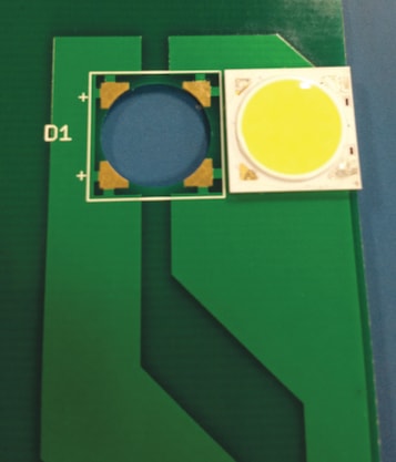
A third example is a chip-on-board or CoB, as shown in Figure 4. The OEM wants to use a different kind of flux and/or alloy for the solder paste. Then the OEM customer wants to learn how effectively that CoB will undergo assembly processes. A similar DOE is evaluating an FR4 version of a metal core board. In this case, the OEM is interested in how and how much heat transfers when this board is subjected to different temperature cycles, thermal profiles, and soak levels.
Each DOE is unique in the sense that it is characterized by an OEM’s special requirements. However, all DOEs share a variety of different PCB design and assembly aspects and stages such as board finishes, temperature cycles, thermal profiles, solder pastes, different fluxes, chemical agents, and so on.
Considerations
A medical electronics OEM seeking the right EMS provider to perform its DOEs should choose an EMS company that has latitude, flexibility, and most important, technical experience. It’s helpful if the EMS provider has a strong and entrepreneurial mindset to take on new projects and new challenges. Persistence is the linchpin for accomplishing successful DOEs. The understanding between the EMS provider and OEM in these instances is the fact the project at hand is floating in unchartered waters. All the answers aren’t there. But the critical ingredients are available, and those are tenacity, knowledge, basic information, and some idea of the direction that needs to be taken.
This article was written by Zulki Khan, President and Founder, NexLogic Technologies, Inc., San Jose, CA. For more information, Click Here
