
Fiber-optic curvature sensing has great potential for a number of medical and industrial applications because alternative solutions are practically nonexistent, at least for similar small sizes. FBGS has shown the feasibility of performing curvature sensing using a newly developed multicore fiber (MCF) inscribed with draw-tower gratings (DTG®).
The resulting MCF-DTG® exhibits the advantageous properties of a standard single-core DTG, including the option for system designers and integrators to take advantage of the densely configured arrays of DTGs. The emergence of the MCF-DTG is destined to present a paradigm shift in curvature, shape, and deflection sensing and will for many applications be the preferred solution over conventional methods.
The DTG Approach
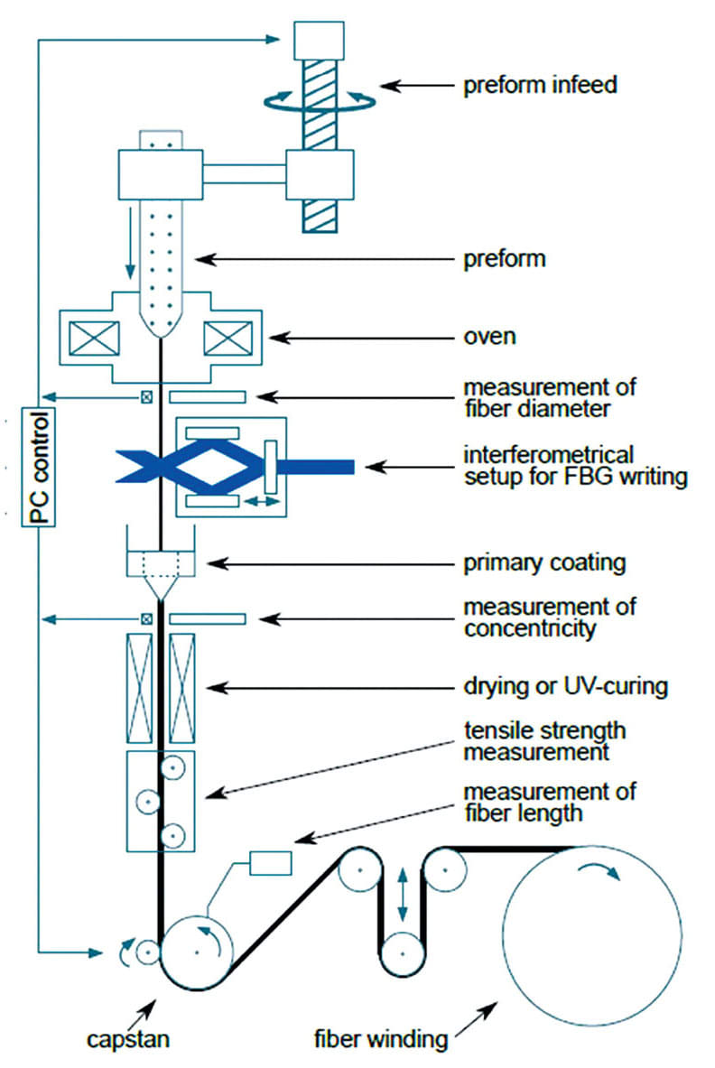
The DTG approach vertically integrates the drawing process of the optical fiber with the inscription and coating steps in a single setup as seen in Figure 1.1 The fully automated process can inscribe a high-density quasi-distributed array of DTGs along the length of the optical fiber. This array can be configured of different Bragg wavelengths or with a uniform wavelength profile.
Based on the dynamic nature of the draw-tower inscription process, the typical length of an inscribed DTG can range from 1 to 10 mm, while their centers’ separation typically starts from 10 mm. Shorter spacing down to ~1.5 mm has also been achieved with a minor modification to the setup. Individual reflectivity can range from 0.01 up to 25 percent. A few advantages of the DTG process are as follows:
- Fabricated sensors exhibit ultimate robustness with a uniform and smooth surface.
- Dense and long arrays of DTGs can be inscribed and can be configured in different cross-sectional structures.
- The process is uniquely positioned for both small- and large-volume production (up to several tens of thousands DTGs per day), and costs are reduced.
Multicore Fiber DTGs
MCFs are specially configured optical fibers with multiple single-mode cores sharing the same cladding. The cores can all be addressed individually via a customized fiber optic fan-out element.
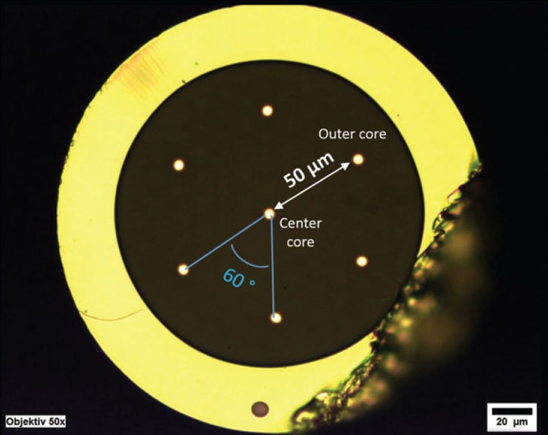
A uniquely produced cross-sectional profile of a seven-core (one central, six outer symmetrically spaced) MCF-DTG sample is shown in Figure 2. Its cladding diameter is 150 μm with an average core diameter around 5 μm and an outer diameter of a unique coating (Ormocer®) of about 215 μm.2 A significant parameter to be considered is the distance between its center and outer cores, which is about 50 μm.
The DTG fabrication process has successfully been adopted for writing fiber Bragg gratings (FBGs) into the MCFs.3 Hence, one can simultaneously produce DTGs of specific configurations in all seven cores at the same exact axial location and with the same wavelength. This precision in the inscription of these high-density DTGs in the MCF represents a major milestone.
Curvature Sensing with MCF-DTGs
A curvature sensing system comprises a sensor, an interrogator, and the software that manages all the algorithms for data readout and processing. The key constituent for this type of sensing is based on simultaneous and real-time monitoring of the induced strain in a minimum of three outer cores of the MCF-DTG.
Depending on the curvature orientation of the MCF, some of the DTGs on the outer cores will experience a relative longitudinal tension or compression with respect to the central core and, therefore, will register positive- or negative-induced strain changes, respectively. To calculate the local curvature (or bending radius), the relative strains are measured, processed, and analyzed. To reconstruct the curvature profile of an MCF, the gathered data can then be plotted as function of the DTG position along the optical fiber.
Algorithms for calculating curvature have been well-presented in the literature.4–6 The induced strain in each core is proportional to the curvature and the distance from the outer core to the neutral axis (NA) of the structure. In principle, the NA is an axis that passes through the center of the fiber's cross-section as shown in Figure 3. It represents the points of zero-bending strain, which can be oriented in any direction. To parametrize this degree of freedom, use the angles αn (n=1, 2 or 3) that represent the angular orientation of the nth outer core with respect to the NA. Basically, it is sufficient to know only one angle since the other angles are fixed by design. The distance of each outer core to the NA can be found by making a perpendicular projection of the core position to the NA, which can be expressed in terms of the angle αn and the distance d between the outer core and the central core.
The induced strain εn of the nth outer core can then be expressed as:
εn = (d/R).sin αn
where 1/R represents the curvature C expressed in terms of the bending radius R. This leads to a set of three equations from which R and αn can be calculated irrespective of the longitudinal strain, temperature, and twist of the fiber, as these parameters can all be considered as common-mode effects. At the same time — similar to a single-core DTG — the center core can still be used to monitor the temperature or strain.
For a fixed value of d, the value of the induced strain in the outer core increases linearly with the curvature. Consequently, the curvature sensitivity is constant over the full bending range of the MCF-DTG. The minimum detectable curvature changes for a given d is defined by the resolution of the interrogator, whereas the overall accuracy is not only defined by the interrogator's accuracy but also by the uncertainty and variation on the parameter d over the length of the MCF.
To increase the MCF's curvature sensitivity, the parameter d can be increased. Increasing the cladding diameter will, for example, allow scaling of the parameter d accordingly. Nevertheless, this tuning range is limited by the maximum cladding diameter the drawing process can withstand.
In case the requested sensitivity cannot be achieved using the MCF approach (e.g., industrial applications where very large bending diameters of +100 m need to be monitored), an alternative solution based on a multi-fiber-bundle (MFB) can be considered. The MFB consists of several fibers, which are consolidated in a cable-like structure to achieve a similar measurement concept. In an MFB design, it is easier to enlarge the parameter d.
However, the major drawback of the MFB approach is the error induced by the co-alignment of the different grating positions in the different optical fibers, which reduces the curvature accuracy. In addition, the mechanical stability over time and the operating temperature of the MFB is also more difficult to control but nevertheless is crucial to ensure a consistent strain transfer to the different fiber strands in the MFB. Finally, the overall cost of large volume fabrication, testing, and deployment of the MFB is inherently far more expensive than the MCF-DTG approach because the MFB is composed of at least four individual fibers.
Signal Interrogation Schemes
Two well-established detection schemes — wavelength division multiplexing (WDM) and optical frequency domain reflectometry (OFDR) — are well suited for monitoring the wavelength shift associated with the induced strains of the MCF-DTG sensors. The signals from the individual cores are routed via a specially configured fiber optic fan-out device to separate optical fibers, which can be easily connected to the different channels on the interrogator. These techniques are designed to provide detection speeds up to 100 Hz for OFDR and several kilohertz for WDM.

An OFDR-based system commands an array of densely spaced DTGs with identical wavelengths. Such fiber is also designated as an all grating fiber (AGF).7 The individual reflectivity should be low to avoid any shadowing effects and to allow the propagating signal to reach the last DTG, but high enough to meet the minimal detectable signal threshold at the interrogator. Reflectivity around 0.01 percent is detectable, which permits a maximum number of DTGs on a single channel to reach a few thousand.
Alternatively, the WDM-based system demands unique wavelengths for each MCF-DTG position with an individual reflectivity of 0.1–25 percent. The maximum number of DTGs that can be interrogated simultaneously in one core is typically between 40 and 80 and is constrained by the wavelength range of the interrogator.
The OFDR-based system has the advantage that each channel can perform high sensor-count measurements. However, when it comes down to measurement resolution and accuracy, WDM-based systems are preferred because they are typically a factor of 10 higher in sensitivity and accuracy and are more cost-effective.
Test Data
The WDM technique can identify the exact locations of the DTGs along the length of the optical fiber through the uniquely defined Bragg wavelength for each grating position. As an example, Figure 4 displays the actual spectral data gathered via a WDM-based setup for a four-core MCF-DTG containing 11 DTGs. Note that all of the sensing elements in the same core have a different wavelength, which allows the identification of their position.
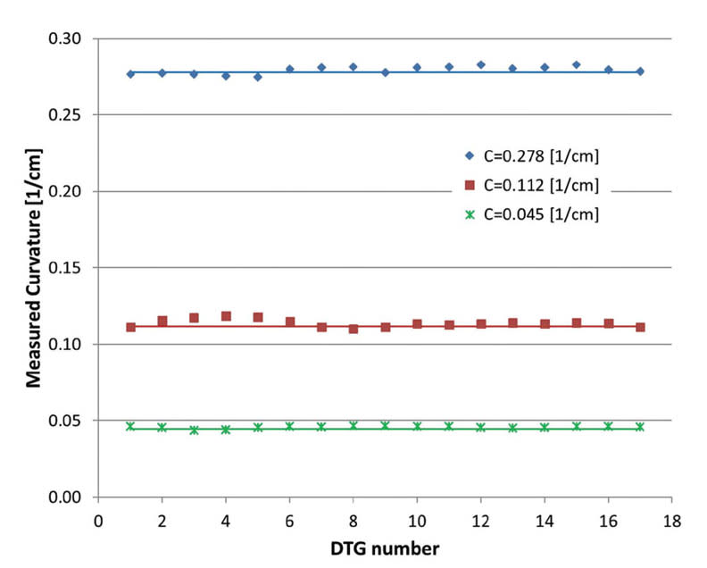
Figure 5 displays data for a WDM-based measurement of several curvatures of an MCF having 17 DTGs each with an 8-mm length and a separation of 10 mm. Each set represents an MCF that was wrapped lightly around a spool of different radii of R = 3.6, 8.95, and 22.5 cm, corresponding to a curvature of C = 0.278, 0.112, and 0.045 [1/cm], respectively. The measured data closely represents the actual curvatures of the spools with some minor fluctuations, which are attributed to an accumulative error stemming from different sources, such as asymmetries in the cross-sectional configuration of the cores’ location with respect the central axis, the variations in the core separations, and other spooling related errors.
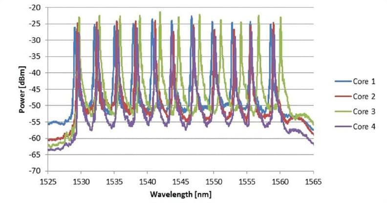
Figure 6 displays a similar MCF, but this time the curvature data is used together with calculated values of the angular parameters αn to reconstruct the 2D and 3D shape profiles using a WDM interrogation system. Depending on the length of the profile to be measured, WDM- or OFDR-based interrogation technologies can be selected. The WDM-based shape sensing offers a cost-effective solution and can, for example, be used for monitoring the tip deflection of a catheter with high accuracy. OFDR provides a higher multiplexing capability, which allows monitoring of the shape of the full catheter profile. However, longer fiber lengths are more prone to becoming twisted; hence, a twisted-core MCF design is typically adopted, whereby the outer cores follow a helix pattern inside the cladding. Such a design makes it possible to compensate for the twisting effect, which is not a common-mode parameter when dealing with shape sensing. The calculation of these shape profiles is beyond the scope of this article but the basic technology is the same.
Related Design Issues
Depending on the application requirements, sensors must meet certain physical properties to fit and navigate their landscape. Current MCF-DTGs with a cladding diameter equal or smaller than 150 μm present a favorable design feature. In addition to its good sensitivity to curvature, it also withstands the stress of tight curvatures (R > 5 mm).
The customization flexibility of the MCF-DTG configuration (number, size, spacing, and layout of cores) and parameters (number, wavelength, length, density, and spacing of FBGs) provides a powerful design feature for optimizing system performance. For curvature sensing along relatively short paths (<25 mm), a higher density MCF-DTG is required. For longer paths, the total number of DTGs also becomes more tangible. For WDM-based measurements, the highest number of DTGs must be below the spectral capacity of the interrogator, while their spatial spacing must be close enough so that curvature information is not missed in between the gratings.
Applications
In general, DTG sensors are a viable alternative to electromechanical strain gages or electrical temperature sensors for applications that demand multiplexing of high number of sensors and overall immunity to environmental conditions. However, a DTG-based sensor can be most effective in applications where sensor robustness, electromagnetic immunity, footprint, weight limitation, dynamic range, and lifetime are of concern. MCF-DTGs are projected to further broaden the application scope of quasidistributed sensors.

A growing interest from the healthcare sector is the delevopment of a more reliable and innovative interventional (diagnostic and therapeutic) tools that can provide better efficacy at a lower cost. This trend is driving the medtech industry to pursue novel and smarter sensors that can be integrated within the minimally invasive gear. The MCF-DTG are well suited for this purpose because of their small size. Their size makes them ideal for integration within introducers, catheters, needles, laparoscopes, endoscopes, and robotic arms with rigid or flexible shafts, especially when disposability or limited reusability is part of the utility projections. These devices are common in applications in which the MCF-DTG sensors can aid the radio-frequency, microwave, laser, or cryogenic ablation procedures. They are also a great option for navigating biopsy and brachytherapy needles under MRI imaging, curvature sensing of endoscopic devices, and delivering medicinal compounds to delicate and confined spaces in vivo, etc.
Conclusion
The successful inscription of densely configured DTG arrays in the MCF has given designers a better outlook for real-time monitoring of quasi-distributed sensing of curvature, deflection, or shape profiles of narrow flexible shafts or thin structures that are sought-after in critical medical and industrial applications. The MCF-DTG uniquely delivers all the advantages of the DTG sensor. In addition, it provides the ability to register curvature and/or shape as well as the ability to remove the effects induced by the indwelling environment, such as temperature and strain induced by axial loading. Furthermore, it positively affects the overall cost of parts, integration, and long-term performance errors and stability. The MCF-DTG presents sensor configuration, that, if properly implemented, can overcome the limitations and concerns exhibited by alternative approaches.
This article was written by Nadhir Kosa, PhD, Director of Business Development, Biomedical & Special Markets;1 Bram Van Hoe, PhD, Director of Sales & Marketing;1 and Jan Van Roosbroeck, PhD, R&D Manager;1 Christian Voigtländer, R&D Manager;2 Johan Vlekken, PhD, Chief Technology Officer;1 and Eric Lindner, PhD, Chief Executive Officer.1,2 1. FBGS International NV, Geel, Belgium; 2. FBGS Technologies GmbH, Jena, Germany. Kosa can be reached at
References
- E. Lindner, "Tailored Draw Tower Gratings (DTG`s) and their Application in Sensing Technologies," in Advanced Photonics, Optical Society of America, 2014, paper BW3D.1.
- http://www.fbgs.com/technology/why-wehave-chosen-to-use-an-ormocer-coating/
- B. Van Hoe et al., “Distributed strain and curvature measurements based on tailored draw tower gratings,” IEEE Avionics and Vehicle Fiber-Optics and Photonics Conference (AVFOP), pp. 285–286, 2016.
- P. Leyendecker et al., “Fiber Optic Curvature Sensor,” in IEEE Sensors 2014 Proceedings, pp. 43–46, 2014.
- J. Moore, “Shape Sensing Using Multi-core Fiber,” in Optical Fiber Communication Conference, OSA Technical Digest (Optical Society of America, 2015), paper Th1C.2.
- M. J. Gander, W. N. MacPherson, R. McBride, J. D. C. Jones, L. Zhang, I. Bennion, P. M. Blanchard, J. Gurnett, and A. H. Greenaway, “Bend measurement using Bragg gratings in multi-core fiber,” Electron. Lett. 36(2), 120–121 (2000).
- http://www.fbgs.com/products/allgrating-fiber/overview/

