Precision electroforming is an additive process in which two and three-dimensional (3D) microstructures are formed by electrochemically depositing metal into a precisely formed photoresist mold. Electroforming is ideal for fabricating micron-scale, metallic components, as well as for making injection molds used for forming non-metallic microstructures with nano-scale features.

Unlimited Geometries
The supplier can create 3D, single or complex, multilayer microstructures with very high aspect ratios. Table 1 shows photoresist aspect ratio guidelines. The geometric options are unlimited because the X, Y, Z structural plane of each layer is formed by a photoresist image. Such structures may be freestanding or connected to comb-like supports to facilitate handling or fixture mounting.
The electroforming process employs a wide variety of plated materials and commercially available photoresists to produce 3D microstructures with very high aspect ratios possible. Note that aspect ratio depends on the photoresist pattern.
Sample applications can include micronozzles, microstructures, slits, micro screen/mesh, disks, and embossing tools.
The materials commonly used include nickel cobalt, nickel, copper, pure gold, and hard gold.
Here’s How It Works

For example, if the photoresist were patterned in the shape of a donut, the resulting structure would have the shape of a cylinder with walls as thick as the donut and a central opening only as wide as the donut hole.
If the finished devices are to be freestanding, they can be peeled off the mandrel once all metal is added. Alternatively, the component may remain attached (to a fixture, for example).
Depositing metal to the height of the photoresist layer results in a cylinder with vertical walls. Sometimes, however, the desired shape is not vertical but rather cone (pyramid) shaped. That might be the case, for example, when fabricating a micronozzle. Then the photoresist “walls” would be lower, so that metal deposits both vertically (to the extent the nozzle is long) and out to the sides (overflowing the photoresist) so that the nozzle is wider toward the bottom than toward the top, forming a pyramid. More metal deposits nearer the bottom because the structure builds up from the bottom.
Depending on the resolution of the mask image, electroformed features can be extremely tiny, even down to 10 microns. The size of openings, like a nozzle orifice, can be as small as 25 microns. Hole diameter depends on the amount of metal deposited around an opening in the photoresist. As more metal is added, diameters shrink, eventually to zero if enough metal were to be added. Opening size, however, can be extremely well controlled based on variables that (among other things) determine the rate of metal deposition. These variables are among a number of factors critical to customers’ success in achieving their design goals.
Giving Customers What They Want
Medical device customers have very high standards when it comes to selecting the source of their electroformed parts. They look for extreme capabilities in areas like:
- Feature size
- Feature controllability
- Surface uniformity
- Batch consistency
- Component ruggedness

- The chemical makeup of the electrolyte bath
- The chemical balance and pH of the bath
- Cleanliness of the bath
- Bath temperature
- Room temperature
- Current density
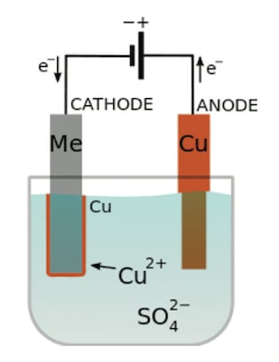
Electroplating uses electrical current to bond metal to metal in an electrolytic cell, or container, filled with a chemical mixture called a bath. Besides the bath the cell also contains a positively charged source of metal (the anode) and a negatively charged target (the cathode). In electroforming, the cathode is the mandrel’s metal layer and any metal deposited there. (See Figure 1)
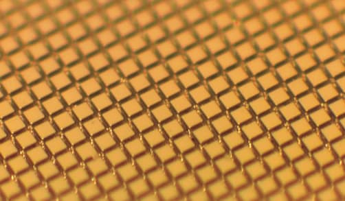
An almost infinite variety of microstructures can be electroformed, depending on the pattern and dimensions of the photoresist layer. (See Figures 2 and 3)
The electrolytic bath consists of dissolved salts (copper sulfate, for example) that provide ions to enable the flow of electric current through the bath from anode to cathode. The electric current ionizes the anode’s metal; the ions are dissolved in the bath and then flow to the cathode where they bond to, and build up, the electroformed part. The rate at which metal is added (plated) to the cathode is proportionate to the current density. Therefore, the more electric current applied, the faster the plating.

Other stress-causing factors include the makeup, balance, and pH of the bath’s chemical mixture. In addition to the various salts that enable ionization and current flow, other chemicals in the bath include levelers that help ensure the finished surface is smooth (level). If the salts, levelers, and other chemicals are out of balance (such as if there’s too much chloride) they can cause excessive stress. Stress also rises sharply at pH values above 6.0. Temperature also impacts stress, including bath temperature, room temperature, and the difference between the two.
Another reason chemical balance is key is so that salts do not precipitate out of the bath, as these solids could strike the part and cause damage. Environmental dust could also cause damage if it were allowed to get into the bath. Even a 2-micron size piece of lint can do serious damage to a circuit with features in the 5-micron range. To protect against such hazards, your supplier should have developed and strictly follow a number of best-manufacturing practices, process controls, and quality assurance procedures.
Key Electroforming Success Factors
Here are five of the most significant ways your supplier can ensure the quality of its electroforming process.
Knowledge capture and reuse: When a customer has a new project, the supplier’s experience can provide quick and clear insights into the process design and set-up for best results at the lowest risk with the fastest turnaround.
Constant monitoring: The supplier should continually monitor key parameters like current density, chemical balance, and bath and ambient temperature to ensure that the process stays on track with the recipe prescribed for a particular part. This helps achieve uniform results consistent with a given recipe, but also provides a benchmark against which to potentially fine tune the recipe for even better results.
Visual parts inspection: Electroplating is a “fluid” process. Conditions of the bath will drift with time and with the number of batches processed. That’s why the supplier should visually inspect parts as they come out of the bath to make sure that specifications such as geometry, surface smoothness, and feature size are being met. If they’re not being met, they should take mitigating measures such as replacing bath filters, replacing the bath, or adjusting the recipe.
Quality of manufacturing facilities: Whether your electroformed part can meet design specifications, perform as intended in your application, or stand up to environmental challenges has a lot to do with the capabilities of the manufacturing equipment and processes involved in making the part. Those capabilities include state-of-the-art systems for computer-aided design, photolithography masking and imaging, the layering of metals at an almost atomic level, and ultrapure manufacturing equipment and clean rooms.
Electroforming manufacturing experience: Advanced skills are required throughout the electroforming production cycle. Product and process engineers must know what will work and what won’t so as to meet the application’s design, mechanical, environmental, and cost criteria in high volumes at high yield—and within tight market windows.
This article was written by Jeremy Lug, Engineering Manager, Metrigraphics LLC, Wilmington, MA. For more information, Click Here .


