The fourth edition IEC/EN 60601-1-2 (4th Edition) will become a mandatory standard covering safety for medical devices on December 31, 2018.1,2 As with any new standard edition, there are changes that necessitate additional evaluations of the product beyond those required by the previous edition. Although emission and immunity tests for medical products are very similar to those applied to other product types, such as radio equipment, networking equipment and multimedia equipment, IEC 60601-1-2 requires that basic safety and essential performance of the medical device be maintained as opposed to the EMC compliance for other type of products. This is reflected in the title of 4th edition.
Basic safety and essential performance are derived from the risk management process. These terms are described in IEC 60601-1. The outcome of this process should identify the performance associated with each function of the device that is necessary to maintain the risks within acceptable limits.
Having determined the functions and their associated parameters that need to be evaluated during immunity tests, the next step is to develop a test plan that addresses how each function will be evaluated, identify those functions that can be evaluated simultaneously, and provide the cycle time for each of these functions. These are only some of the items that must be included in the test plan. The form of the test plan is now specified in Annex G of the 4th edition. Before testing can begin, the test plan needs to be provided to the test lab (section 6.2 of the 4th edition).
Summary of the Changes in the 4th Edition
Below is a summary of the emission and immunity test requirements in the standard. The 4th edition includes three environments based on intended use (professional healthcare, home healthcare, and special). Only the professional and home healthcare environments are listed in Table 1. The use of special environment is handled in the risk management process and can result in using different test levels than those indicated in the 4th edition. The items indicated with an asterisk in Table 1 indicate that this is something changed, is new, or was expanded for the 4th edition.
The ESD levels have been increased from ±6 to ±8 kV for contact discharges and from ±8 to ±15 kV for air discharges.
The highest frequency for radiated immunity has been increased from 2,500 to 2,700 MHz and a new “proximity” test was added. Additionally, the test levels have changed, and the modulation frequency is specified only as 1 kHz. The 2 Hz modulation frequency that was specified for certain equipment in the previous edition is not in the 4th edition. However, if the risk management process identifies a different modulation frequency, it should be used. If the product incorporates a wireless receiver, an exclusion band shall not be used for the receiver operating frequency.

The EFT/B test is specified to be performed using a 100 kHz repetition frequency. The previous version of the standard did not specify the rate, so it may be that 5 kHz was used. A review of the existing test report should be performed to determine the rate that was used.
The AC power port surge test levels have not changed from those in the previous edition. DC power ports that are longer than 3 m and signal ports that connect to outside cables are now subject to a surge test.
The conducted immunity frequency range and test levels did not change from the previous edition. However, a new test level at certain ISM and amateur band frequencies of 6 Vrms has been added. The modulation frequency is specified only at 1 kHz. The 2 Hz modulation frequency that was specified for certain equipment in the previous edition is not in the 4th edition. However, if the risk management process identifies a different modulation frequency, it should be used.
The power frequency magnetic fields test level has been increased from 3 to 30 A/m. However, the 4th edition states that the test applies only to products with magnetically sensitive components or circuitry.
Voltage dips have changed from those in the previous edition, which were <5 percent for ½ cycle, 40 percent for 5 cycles, and 70 percent for 25 cycles. Only the dip to 70 percent of nominal voltage was not changed. Voltage interruptions changed only in that the previous edition allowed the interruption to be performed with up to a 5 percent residual voltage. If tests were performed for the previous version at 0 percent, the results comply with the 4th edition.
The transient conduction on DC power tests, which are new in the 4th edition, only apply to products intended to be installed in vehicles with 12 or 24 V electrical systems.
It should also be noted that the 4th edition includes a table delineating the voltage and frequency of the AC supply mains to be used during each test. Some of the tests specified in the previous edition to be performed at multiple voltages and frequencies are only required to be tested at a single voltage and frequency. It may be that other economies require different voltages and/or frequencies than those listed in the standard, so these should be delineated in the test plan.
The other area in which the 4th edition is different from the previous edition is in the requirements for marking and instructions for use contained in Clause 5 of the 4th edition. Gone are the requirements for tables like those in the previous edition. However, many of the statements required to be included in the instructions for use are similar. A test laboratory can conduct a review of the product and documentation provided to an end user against these requirements.
Radio Functions
Addressing radio functions is not something that is new in the 4th edition but it is often overlooked. What do you do when a radio module is incorporated in a medical device? IEC/EN 60601-1-2 has wording that addresses the use of radios in a medical device. An exemption for the main transmit signal from the radiated emissions limits (provided that they meet the national requirements) is given, but all other emissions must meet the radiated emissions limits of IEC/EN 60601-1-2. Note: There are many cases where the radio standard's limits for transmitter radiated spurious emissions are less restrictive than the IEC/EN 60601-1-2 limits.
The radio function must be addressed during the testing of the complete product. Some of the tests that were likely performed on the radio module alone would still be representative of the use in the end product. However, radiated emissions and immunity tests performed on the radio module are usually not performed or the results do not consider the EMC effects of the integration, so tests must be performed on the product with the radio module operating as in normal use and in a mode to make sure no unintentional transmissions occur.
Cycle Time Considerations
Another tip that is not new in the 4th edition addresses cycle time for each of the functions to be evaluated, which can have a significant impact on the time needed to perform radiated and conducted immunity tests. The standard requires that the dwell time at each frequency step be long enough for the product to be exercised and respond. For example, if a device processes data by taking multiple samples and averaging them and providing a result every 60 seconds, the dwell time at each frequency step would be 60 seconds. Note that the dwell time must be specified in the test plan.
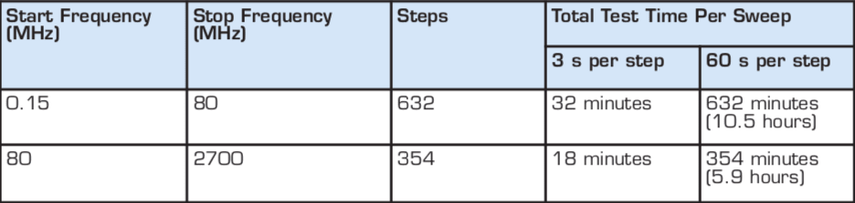
Both radiated and conducted immunity tests use a frequency step size of 1 percent and a typical sweep rate of 1–3 s. Table 2 shows the number of steps in the frequency ranges for both conducted immunity (0.15–80 MHz) and radiated immunity (80–2,700 MHz) and compares the total test time for a nominal sweep rate three seconds per frequency versus a sweep rate requiring 60 seconds per frequency.
The test times for conducted immunity in Table 1 are compounded by the number of interface cables, with the test typically applied to each interface cable in turn.
For radiated immunity, the device is typically tested four times (each side of the device facing the transmitting antenna) sides, but portable devices should be tested on all six sides. Each side is tested twice, once with the transmitting antenna vertically polarized and once with the antenna horizontally polarized. A portable device, therefore, would be tested a total of 12 times. For transient immunity tests, the issue of cycle time can also affect test times since the application of the transient cannot be synchronized to the “most susceptible” operating cycle of the device. Depending on the function/process being evaluated, the test may need to be applied over multiple cycles.
It may be possible to implement test modes in advance of testing that use fewer samples (thereby reducing the cycle time of the device) or allow multiple functions to be monitored simultaneously. It must be noted that test modes have to be fully representative of the real-world application, so it may not always be possible to implement test-time-reducing features and meet the requirements of the notified body or government agency responsible for reviewing the test data.
Essential Performance Case Studies
Case #1: Infusion Pump. Infusion pumps have their own product-specific basic standard: IEC/EN 60601-2-24. Although this standard makes some modifications to the requirements of basic standard IEC/EN 60601-1-2, the essential performance, risk analysis, and their effects on the EMC immunity test plan are representative of issues for all medical devices.
The essential performance of the pump was identified as providing fluid at a flow rate that remained within tolerance (the tolerance was defined based on technical judgment from within the manufacturer's expertise in this specific medical application). In addition, the pumps ability to detect certain error conditions (such as air in the line or line occlusions) and create an alarm was also considered a part of essential performance. This meant that two modes had be tested — normal mode (with the pump infusing at a predetermined rate) and alarm mode (with various types of errors introduced into the system).
To address the flow-rate evaluation, the manufacturer first considered the use of a scale to determine the volume infused over a certain period of time. This method was considered inappropriate because short duration changes in the instantaneous flow rate might go unnoticed when the weight of fluid delivered was averaged over the duration of a test. To counter this, the manufacturer developed an additional device to measure flow rate and to give a visual indication if the flow rate went out of tolerance. The flow meter had to be tested for immunity prior to performing the test to determine whether there were any susceptibilities prior to testing the final product to ensure that any flow-rate alarms were because of the device susceptibility and not due to the monitoring equipment.
The alarm conduction tests required no special test equipment since the error conditions could be recreated by manually injecting air into the line or pinching off the fluid line. As these conditions could not be recreated on a continuous basis, the manufacturer followed our recommendations to run these tests at spot frequencies for radiated and conducted immunity, with the frequencies selected based on the operating frequencies of ISM and radio devices in the hospital environment. For transient tests (ESD, surge, voltage dips, and interruptions), as the transient phenomena are all short duration events and the error condition would be a long duration event, the primary concern was that these transients did not damage the error-detection circuitry or inhibit the alarm. The ability to detect the error conditions was verified before and after applying each phenomenon, while also verifying that the transient phenomena did not reset the alarm condition.
Prior to implementing the above test plan, there was some discussion on the possibility of having a method of monitoring the alarm circuitry during “normal” operation to verify that they were not susceptible to the applied phenomena (for example, by indication of the analog output from the circuit). This was not possible on the current product line but may be implemented in future products. While it may not alleviate testing in the alarm mode, it might reduce the number of tests required by allowing selection of reduced tests on the mode based on the areas where the circuits showed susceptibility.
Case #2: Telemetry System. This device contained a sensor and would periodically send data acquired by the sensor to a remote data logging device. In normal operation, the device would transmit every 2 minutes; however, the interval could be adjusted for the device to transmit every 90 seconds. It was not possible to reduce this sampling time any further because the device required this as a minimum sampling time to avoid producing invalid data.
Although there were no complicated test configuration issues with this device, the fact that the dwell time could be reduced from 120 to 90 seconds represented a significant test time savings. This case also brought up the issue of an exclusion band for testing. The 4th edition states that degradation in performance around the receiver operating frequency of the device under test can occur during radiated RF immunity tests, so this is allowed. However, the basic safety and essential performance requirements must still be met.
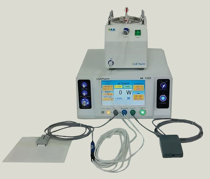
Case #3: Ablation System. This piece of medical equipment is designed to use RF heating to cauterize during surgical procedures. The risk management process resulted in identifying two possible problems that might result in an unacceptable safety risk during operation — the first was if the power setting should change or if the device should power-on unintentionally. It was determined that the RF switching off unintentionally was not a risk provided that the instrument indicated that the RF was off and did not re-initiate without manual control.
Two test modes were, therefore, tested. The first was with the power set at a midpoint to allow the displayed power to be monitored for an unacceptable increase or decrease. The second mode was with the device operating in a standby mode to ensure that it did not switch on the RF unintentionally. By providing two samples, radiated immunity was performed on both modes simultaneously to reduce test time.
Case #4: Home Use Patient Monitoring System. The risk management process for this product concluded that there were no functions that were considered essential to the safety of the patient. Any information obtained by the system would be evaluated on a case-by-case basis, and the system was to be used to provide additional patient information between outpatient visits to the physician. Any abnormal data recorded by the system would be evaluated by a physician who, in turn, would run additional tests before making a diagnosis and prescribing treatment.
In this case, the requirements state that it is not necessary to perform immunity tests to declare compliance. However, the manufacturer still wanted to know whether the product was susceptible, so testing was performed. The performance criteria were not related to essential performance, but to anticipated customer expectations.
Summary
For most products, performing the assessment against the 4th edition will require testing and updates to documentation supplied to the end user. The importance of the risk management process has been highlighted in this article.
Product-specific knowledge and, in many cases, medical expertise are required to clearly identify basic safety and essential performance and minimize the number of functions and test times that need to be used when evaluating the product for susceptibility to the EMC phenomena described in IEC/EN 60601-1-2. The compliance of radios must also be part of an assessment of the product both with regard to basic safety and essential performance and EMC.
References
- FDA will accept declarations of conformity in support of premarket submissions using IEC 60601-1-2 Edition 3 until December 31, 2018. After this date period, declarations of conformity must be to Edition 4. www.accessdata.fda.gov
- Date of cessation of presumption of conformity of edition 3 is December 31, 2018. ec.europa.eu
This article was written by David Bare, a chief engineer at NTS in the company's Fremont, CA, lab. For more information, Click Here .