Most medical electronic systems now depend on combinations of hardware and software, forming elaborate mechatronic systems that both monitor and regulate patient health metrics. To manage mechatronic challenges, product designs must seamlessly integrate embedded and application software, analog and digital hardware, and mechanical components. Unfortunately, successfully integrating and verifying complex systems is often costly in terms of time, money, and engineering resources.
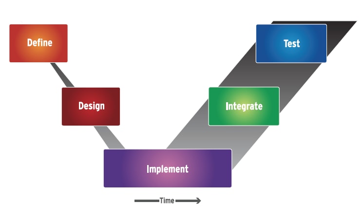
This is an inherently sequential process where verification and validation is not complete until the end, as the “time” axis indicates (Fig. 1). Since regulation does not permit any substitute for final “serial #0” physical system verification and validation, most companies have tried to implement the V process with the goal of minimizing the time from design to physical realization. Writing requirements down in a document based on previous experience and expert knowledge is viewed as faster than creating a behavioral model of the requirements, executing them, and performing simulations and dynamic analysis.
The result is a “paper”-driven, frontend process. The requirements and system architectures are done on “paper” elements such as documents, static diagrams, and requirement lists, which of course are electronically created, stored, indexed, and linked, but are not qualitatively different from what was done many decades ago with a pencil, ruler, typewriter, and paper. A complete analysis and virtual simulation of the entire complex system is not undertaken, as it is viewed as too time-consuming, and efforts are focused on getting to an early physical prototype quickly.
With this approach, the first real visibility of complex system integration problems is reserved for the very final stage of the process — testing the physical, integrated system. The traditional paper-based approach to implementing the V process may have served companies well in the past; however, with today's complex system developments of integrated, interrelated mechatronic elements interacting in non-obvious ways, this is no longer a viable option. A single unplanned redesign caught at the physical integration stage can extend the schedule drastically. The more complex the system, the less likely this approach will result in an FDAapproved design, developed within schedule and budget.
Imagine instead a process where concepts and requirements from all disciplines could be easily tested from the very start, using software modeling techniques and, once proven, would pass from step to step in the process. Teams of experts would work concurrently throughout the technical, system, and process levels, with individual designers concentrating on their specific tasks using the best available tools, while still being able to seamlessly fit into a complete virtual system environment.
Verification would proceed in parallel with design occurring at first completely virtually; then these same virtual tests would be reused when the system is physically verified. Monitoring of compliance with regulatory standards would be integral to every step. Ultimately, all the pieces would be efficiently integrated into a system that works the first time and does not need physical redesigns. This is the vision that gave rise to the innovative Model Driven Development (MDD) tools and processes that are fast gaining favor among system developers. MDD lays the groundwork for an integrated design flow that addresses the complexity challenge once and for all.
The Model Driven Development Approach
In an MDD approach, requirements are connected into the models and their verification suites. Changes to requirements necessitate changes to the models, and this is highlighted immediately in an automated way. The same can be said for interface controls. Instead of existing outside the development environment in some sort of document, in a modeling environment these become active properties of the design itself. Artifacts of the process are another aspect of a program’s documentation. Instead of reports being created by hand (and therefore immediately out of date), the pertinent data from an MDD environment can at any time be viewed, audited, or even automatically generated into a report.
At the very earliest stages of design, the initial idea and its requirements can be captured in a high-level conceptual model, using languages such as UML or SysML. Customer and marketing requirements remain in a requirements database, but these models link directly to them and start to implement the engineering system-level requirements. This blends the initial idea, requirements capture, and conceptual design stages into one new concept validation stage that clarifies and validates the idea, requirements, and concept. This conceptual model — which initially defines only the function’s required behavior — can then be broken down further into a closer representation of the real design at the next level.
At the functional level of the model hierarchy, system-level engineers create executable functions with measurable behaviors that correspond to functional specifications for the design as derived from the system requirements. Interactions and tradeoffs between specifications are explored virtually using functional-level models. Theoretical behaviors are modeled at this level without concern about whether a function will be implemented in hardware or software or which specific components will be used in the design. At this level the models constitute a mix of further broken down UML or SysML combined with algorithmic- or physics-based continuous time models in high-level behavioral VHDL-AMS or similar languages along with rough 3D models of the mechanical aspects of the design.
At the architectural or logical level, teams of system architects, along with domain experts, use model simulations to explore options for implementing the system architecture. Each team can operate in parallel exploring different aspects of the architecture while feeding into and testing against a cohesive complete system model. Different teams start to create more detailed models that are more domain-specific (mechanical, continuous time, discrete, processor scheduling, algorithmic, etc.) as appropriate but remain able to verify them against a cohesive virtual view of the system that is revision controlled and can be traced to the earlier functional level requirements implemented as functional models.
Decisions are then made about which functions will be implemented in embedded software, which in electronic hardware, which functions will communicate virtually via network layers, which will be implemented with a discrete interconnect, and which using other physical disciplines. System engineers test the interfaces between different parts of the design virtually before the design is fully implemented. These tested interfaces are passed down to the implementation level as requirements that each domain must adhere to or request a review by the system engineers. This reduces errors and allows integration issues to be identified and addressed early in the design process.
At the implementation or physical level, each domain-specific engineer drills down into critical areas of functionality, while dealing with the less critical areas more abstractly until the design is closer to completion. In some cases, parts of the implementation designs can be automatically translated from the architectural models into a lower-level implementation (e.g., C, VHDL, etc.) of the actual design, reducing the implementation work to a simple verification task for these cases.
The domain engineers then feed their implementation designs into another more detailed view of the complete virtual system, which allows verification engineers to test the system interfaces and functionality to ensure it meets the requirements before being built. At this stage a process sometimes called a checkerboard approach is used where the architectural level models of the complete system are used, replacing one or a few components at a time at the detailed level.
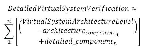 At each step of this process, the original system requirements are traced to measurable attributes of the design and verified. This is supported by the virtual system integration platform, which by combining multiple models and levels of abstraction, provides a way to exercise the behavior of a design at a functional, architectural, or fully implemented level of abstraction or a combination of these levels. In parallel with product design, the verification group is also designing and developing their final physical verification tests against the virtual platform. This test set can run on the system model at any time during the development. Then, when run at the final stages of physical system integration, this final test stage (which so often in traditional flows is the beginning of a very long process of debug) becomes merely a sanity check that the system was built correctly.
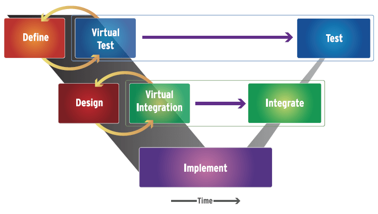
It is important to note that the MDD flow does not require all the participants to use the same tool or the same modeling language. The MDD flow allows the experts to work independently in their own domains, using their own languages (e.g., UML, SysML, Verilog, VHDL, VHDL-AMS, C, SystemC, C++, Java, mscript, etc.) and tools, as they would prefer to do. But, the models they produce can be integrated into a broader system architecture model and executed in any simulator that supports all the chosen standards concurrently or by use of a simulation backplane that connects multiple, domain-specific simulators together into a live, concurrently executing meta simulator. This same sort of virtual collaboration can extend from integrators to suppliers to contractors. Models become the mechanism to collaborate and verify both function and progress at any stage of development. (Fig. 2)
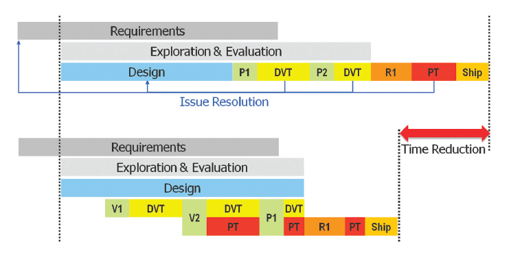
Additionally, while it may seem counter-intuitive, adding time to the schedule up front by delaying the creation of the first physical prototypes of a system and implementing an MDD process on top of the traditional V, it actually reduces the total real-world time from start to FDA-cleared product. Months are shaved off the backend test development and test processes and, due to the significantly higher probability of the first pass success, FDA clearance is actually achieved earlier. (Fig. 3)
Summary
Collaborative MDD will not literally force mechanical, electrical, electronic, and software engineers to sit down in the same room, talk, and jointly work on a program. Instead, it creates a virtual environment that automates this collaboration, transparently. MDD technology gives the system integrator an effective platform to communicate the overall system requirements and individual component specifications. It can also tie project management into development and automate mundane and time-consuming tasks, so designers can spend their time doing what they do best: designing.
This article was written by John Vargas, Systems Architect at Mentor Graphics Corporation, Wilsonville, OR. For more information about model driven development, visit http://info.hotims.com/40432-164 .
